I've spent a good chunk of the day asking myself if we have a bona fide tool mystery on our hands or if I'm just stupid, or both, or all three. Either way, I can't find anything representing this tool in "Salaman's Dictionary of Woodworking Tools" which is my go-to volume for solving these kinds of riddles.
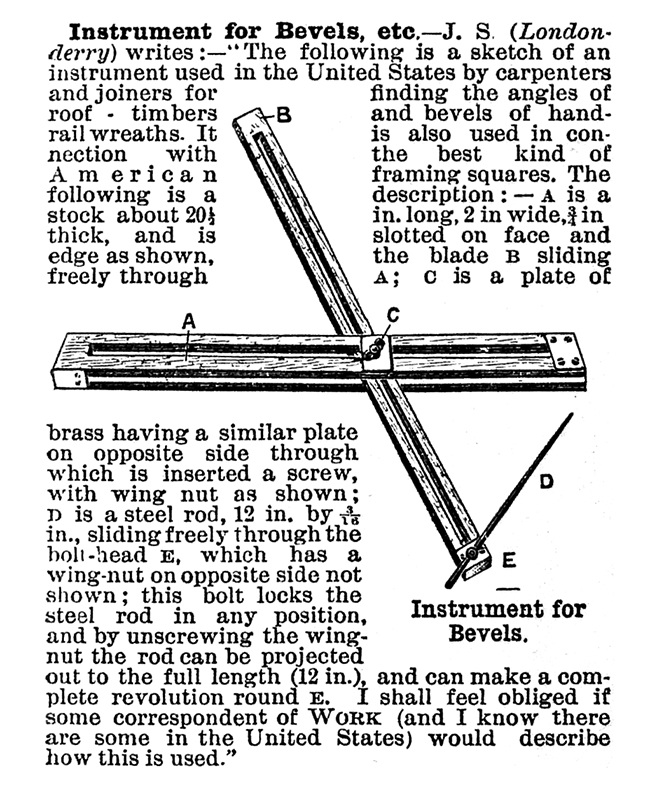
Having access to as-yet un-PDF'd originals, I sped through the upcoming SHOP sections to see if there was a reply from any of the magazine editors or correspondents. I got bupkis, and as result, I'll be obsessed with this thing until I find the answer. I put it to you, loyal workateers. Does anyone know how to use one of these? I imagine that in many ways, it's similar to a sliding t-bevel, except I'm uncertain how the addition of the position-adjustable steel rod is put to use. Further, it is written that the instrument is used "in connection with the best kind of American framing squares." Perhaps someone familiar with the act of setting-out joinery for handrail wreaths will be able to enlighten us. There's a comments section below the entry in case you didn't know.
Disclaimer: Articles in Work: The Illustrated Weekly Journal for Mechanics describe materials and methods that would not be considered safe or advisable today. We are not responsible for the content of these magazines, and cannot take any responsibility for anyone attempting projects or procedures described therein.
The first issue of Work was published on March 23rd, 1889. The goal of this project is to release digital copies of the individual issues starting on the same date in 2012, effectively republishing the materials 123 years to the day from their original release.
The original printing was on thin, inexpensive paper. There are many cases of uneven inking and bleed-through from the page behind. Our copies of Work come from bound library volumes of these issues and are subject to unfavorable trimming, missing covers, etc. To minimize harm to these fragile volumes, we've undertaken the task of scanning the books ourselves. We do considerable post processing of the scans to make them clear but please bear with us if a margin is clipped too close, or a few words are unreadable. We would like to thank James Vasile and Karl Fogel for their help in supplying us with a book scanner and generally enabling this project to get off the ground.
You are welcome to download, print, and pretty much do what you want with the scan for your own personal purposes. Feel free to post a link or a copy on your blog or website. All we ask is a link back to the original project and this blog. We are not answering requests for commercial downloads or reprinting at this time.
Looking at the diagram and reading the description, I'd guess that it would use the roof pitch to find the angle. For example, take a 9/12 pitch roof. The user would probably set the steel bar to 9 inches where it touches the side of the sliding stick. If the steel bar is at a right angle to the sliding stick, then the user would swing the sliding stick until the steel bar hits the outer stick while lining up the 12 inch marking on the sliding stick before clamping it down. That would form the desired roof angle.
I imagine it was faster for carpenters to simply set the roof pitch using the sides of their carpenter's square and then set a bevel gauge to that.


 Joel's Blog
 Built-It Blog
 Video Roundup
 Classes & Events
 Work Magazine
I imagine it was faster for carpenters to simply set the roof pitch using the sides of their carpenter's square and then set a bevel gauge to that.